Original Link: https://www.anandtech.com/show/6777/understanding-camera-optics-smartphone-camera-trends
Understanding Camera Optics & Smartphone Camera Trends, A Presentation by Brian Klug
by Brian Klug on February 22, 2013 5:04 PM EST- Posted in
- camera
- Smartphones
- Android
- Mobile
Recently I was asked to give a presentation about smartphone imaging and optics at a small industry event, and given my background I was more than willing to comply. At the time, there was no particular product or announcement that I crafted this presentation for, but I thought it worth sharing beyond just the event itself, especially in the recent context of the HTC One. The high level idea of the presentation was to provide a high level primer for both a discussion about camera optics and general smartphone imaging trends and catalyze some discussion.
For readers here I think this is a great primer for what the state of things looks like if you’re not paying super close attention to smartphone cameras, and also the imaging chain at a high level on a mobile device.
Some figures are from of the incredibly useful (never leaves my side in book form or PDF form) Field Guide to Geometrical Optics by John Greivenkamp, a few other are my own or from OmniVision or Wikipedia. I've put the slides into a gallery and gone through them pretty much individually, but if you want the PDF version, you can find it here.
Smartphone Imaging
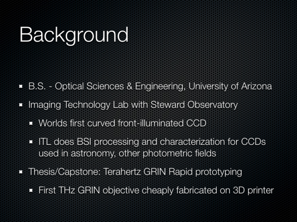
The first two slides are entirely just background about myself and the site. I did my undergrad at the University of Arizona and obtained an Optical Sciences and Engineering bachelors doing the Optoelectronics track. I worked at a few relevant places as an undergrad intern for a few years, and made some THz gradient index lenses at the end. I think it’s a reasonable expectation that everyone who is a reader is also already familiar with AnandTech.
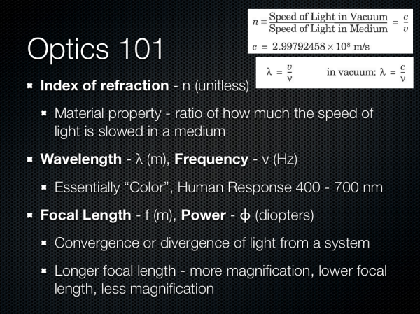
Next up are some definitions of optical terms. I think any discussion about cameras is impossible to have without at least introducing the index of refraction, wavelength, and optical power. I’m sticking very high level here. Numerical index refers of course to how much the speed of light is slowed down in a medium compared to vacuum, this is important for understanding refraction. Wavelength is of course easiest to explain by mentioning color, and optical power refers to how quickly a system converges or diverges an incoming ray of light. I’m also playing fast and loose when talking about magnification here, but again in the camera context it’s easier to explain this way.
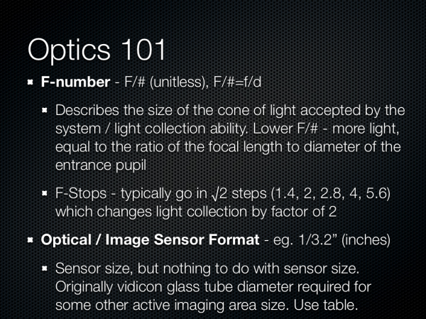
Other good terms are F-number, the so called F-word of optics. Most of the time in the context of cameras we’re talking about working F-number, and the simplest explanation here is that this refers to the light collection ability of an optical system. F-number is defined as the ratio of the focal length to the diameter of the entrance pupil. In addition the normal progression for people who think about cameras is in square root two steps (full stops) which changes the light collection by a factor of two. Finally we have optical format or image sensor format, which is generally in some notation 1/x“ in units of inches. This is the standard format for giving a sensor size, but it doesn’t have anything to do with the actual size of the image circle, and rather traces its roots back to the diameter of a vidicon glass tube. This should be thought of as being analogous to the size class of TV or monitor, and changes from manufacturer to manufacturer, but they’re of the same class and roughly the same size. Also 1/2” would be a bigger sensor than 1/7".
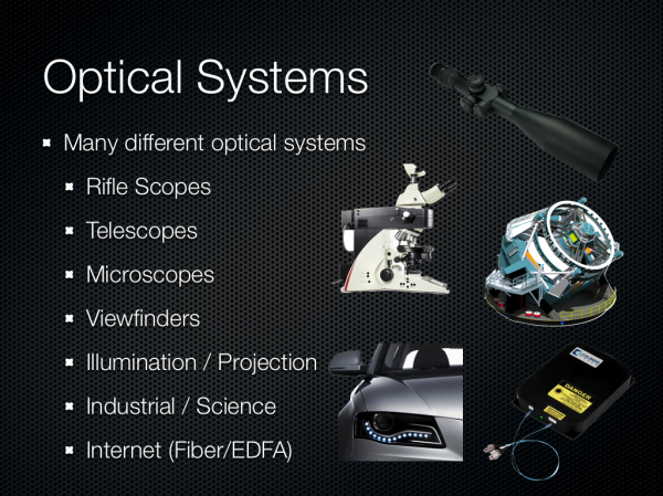
There are many different kinds of optical systems, and since I was originally asked just to talk about optics I wanted to underscore the broad variety of systems. Generally you can fit them into two different groups — those designed to be used with the eye, and those that aren’t. From there you get different categories based on application — projection, imaging, science, and so forth.
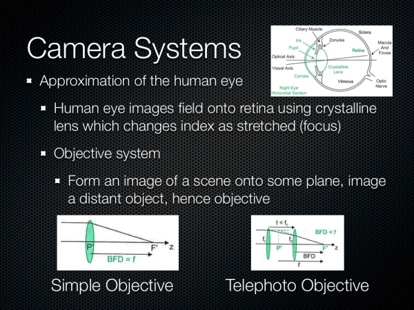
We’re talking about camera systems however, and thus objective systems. This is roughly an approximation of the human eye but instead of the retina the image is formed on a sensor of some kind. Cameras usually implement similar features to the eye as well – a focusing system, iris, then imaging plane.
The Imaging Chain
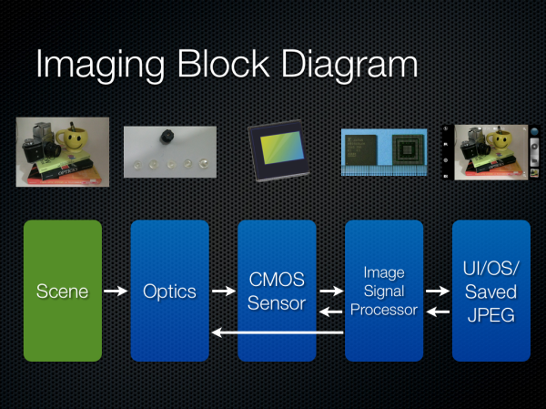
Since we’re talking about a smartphone we must understand the imaging chain, and thus block diagram, and how the blocks work together. There’s a multiplicative effect on quality as we move through the system from left to right. Good execution on the optical system can easily be mitigated away by poor execution on the ISP for example. I put arrows going left to right from some blocks since there’s a closed loop between ISP and the rest of the system.
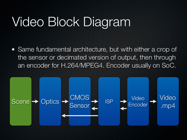
The video block diagram is much the same, but includes an encoder in the chain as well.
Smartphone Cameras: The Constraints
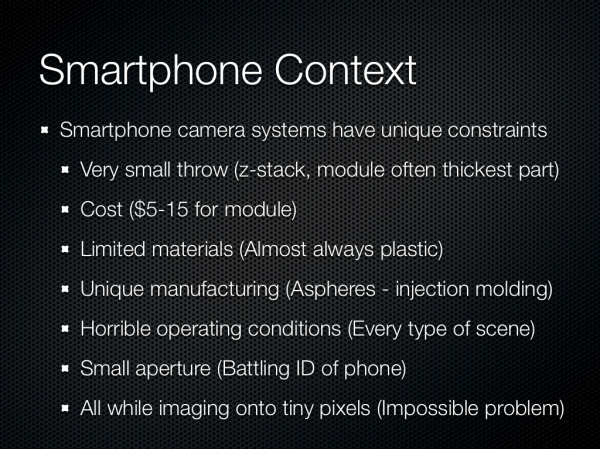
The constraints for a smartphone camera are pretty unique, and I want to emphasize just how much of a difficult problem this is for OEMs. Industrial design and size constraints are pretty much the number one concern — everyone wants a thin device with no camera bump or protrusion, which often leaves the camera module the thickest part of the device. There’s no getting around physics here unfortunately. There’s also the matter of cost, since in a smartphone the camera is just one of a number of other functions. Material constraints due to the first bullet point and manufacturing (plastic injection molded aspherical shapes) also makes smartphone optics unique. All of this then has to image onto tiny pixels.
Starting with the first set of constraints are material choices. Almost all smartphone camera modules (excluding some exceptions from Nokia) the vast majority of camera optics that go into a tiny module are plastic. Generally there are around 2 to 5 elements in the system, and you’ll see a P afterwards for plastic. There aren’t too many optical plastics around to chose from either, but luckily enough one can form a doublet with PMMA as something of a crown (low dispersion) and Polystyrene as a flint (high dispersion) to cancel chromatic aberration. You almost always see some doublet get formed in these systems. Other features of a smartphone are obvious but worth stating, they almost always are fixed focal length, fixed aperture, with no shutter, sometimes with an ND filter (neutral density) and generally not very low F-number. In addition to keep modules thin, focal length is usually very short, which results in wide angle images with lots of distortion. Ideally I think most users want something between 35 mm or 50 mm in 35mm equivalent numbers.
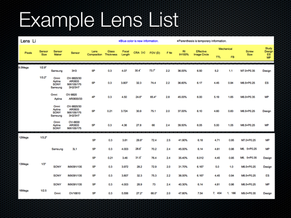
I give an example lens catalog from a manufacturer, you can order these systems premade and designed to a particular sensor. We can see the different metrics of interest, thickness, chief ray angle, field of view, image circle, thickness, and so on.
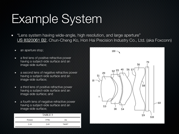
During undergrad a typical homework problem for optical design class would include a patent lens, and then verification of claims about performance. Say what you want about the patent system, but it’s great for getting an idea about what’s out there. I picked a system at random which looks like a front facing smartphone camera system, with wide field of view, F/2.0, and four very aspherical elements.
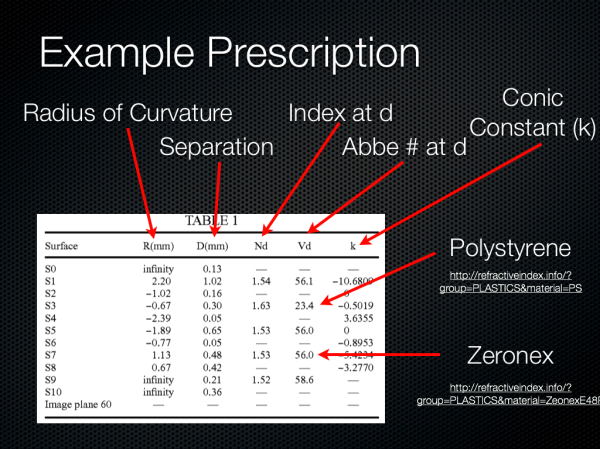
Inside a patent is a prescription for each surface, and the specification here is like almost all others in format. The radius of curvature for each surface, distance between surfaces, index, abbe number (dispersion), and conic constant are supplied. We can see again lots of very aspherical surfaces. Also there’s a doublet right for the first and second element (difference in dispersion and positive followed by negative lens) to correct some chromatic aberrations.
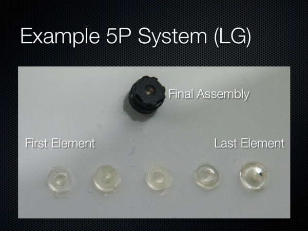
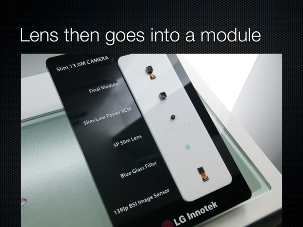
What do these elements look like? Well LG had a nice breakdown of the 5P system used in its Optimus G, and you can see just what the lenses in the system look like.
The Camera Module & CMOS Sensor Trends
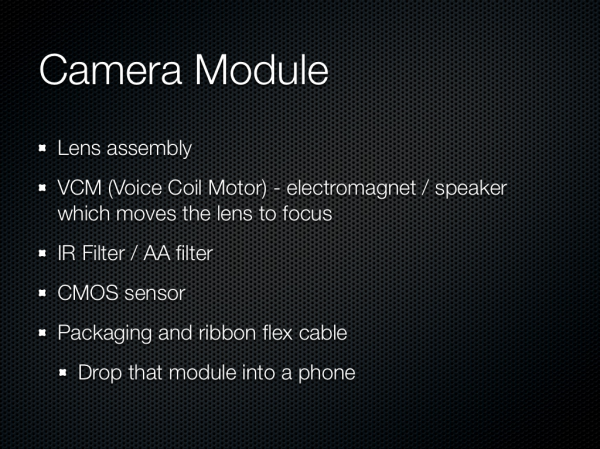
So after we have the lenses, what does that go into? Turns out there is some standardization, and that standardization for packaging is called a module. The module consists of of course our lens system, an IR filter, voice coil motor for focusing, and finally the CMOS and fanout ribbon cable. Fancy systems with OIS will contain a more complicated VCM and also a MEMS gyro somewhere in the module.
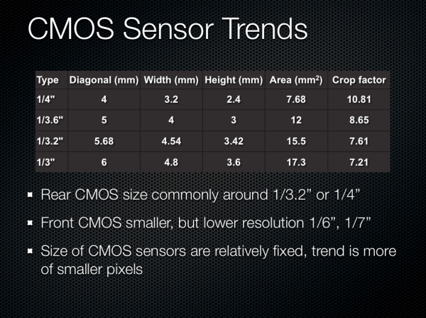
Onto CMOS, which is of course the image sensor itself. Most smartphone CMOSes end up being between 1/4“ and 1/3” in optical format, which is pretty small. There are some outliers for sure, but at the high end this is by far the prevailing trend. Optical format is again something we need to go look at a table for or consult the manufacturer about. Front facing sensors are way smaller, unsurprisingly. The size of the CMOS in most smartphones has been relatively fixed because going to a larger sensor would necessitate a thicker optical system, thus the real trend to increase megapixels has been more of smaller pixels.
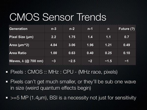
The trend in pixel size has been pretty easy to follow, with each generation going to a different size pixel to drive megapixel counts up. The current generation of modern pixels is around 1.1 microns square, basically any 13 MP smartphone is shipping 1.1 microns, like the Optimus G, and interestingly enough others are using 1.1 microns at 8 MP to drive thinner modules, like the thinner Optimus G option or Nexus 4. The previous generation of 8 MP sensors were using 1.4 micron pixels, and before that at 5 MP we were talking 1.65 or 1.75 micron pixels. Those are pretty tiny pixels, and if you stop and think about a wave of very red light at around 700nm, we’re talking about 1.5 waves with 1.1 micron pixels, around 2 waves at 1.4 microns, and so forth. There’s really not much smaller you can go, it doesn’t make sense to go smaller than one wave.
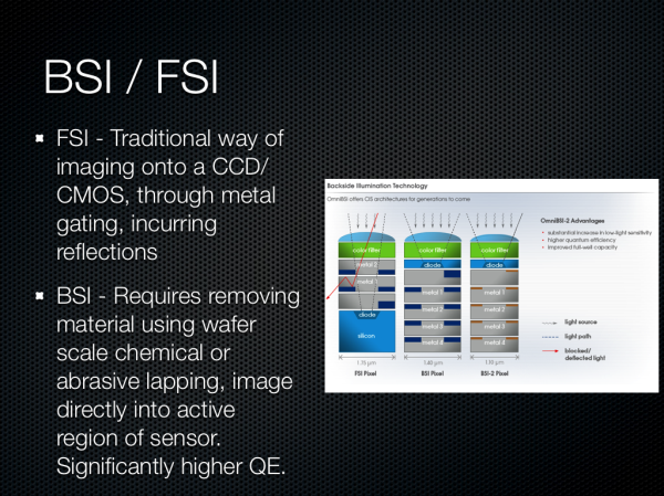
There was a lot of talk about the difference between backside (BSI) and front side illumination (FSI) for systems as well. BSI images directly through silicon into the active region of the pixel, whereas FSI images through metal layers which incur reflections and a smaller area and thus loss of light. BSI has been around for a while in the industrial and scientific field for applications wanting the highest quantum efficiency (conversion of photons to electrons), and while they were adopted in smartphone use to increase the sensitivity (quantum efficiency) of these pixels, there’s an even more important reason. With pixels this small in 2D profile (eg 1.4 x 1.4 microns) the actual geometry of a pixel began to look something like a long hallway, or very tall cylinder. The result would be quantum blur where a photon being imaged onto the surface of the pixel, converted to an electron, might not necessarily map to the appropriate active region underneath - it takes an almost random walk for some distance. In addition the numerical aperture of these pixels wouldn’t be nearly good enough for the systems they would be paired with.
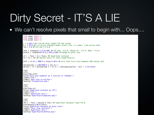
Around the time I received the One X and One S last year, I finally became curious about whether we could ever see nice bokeh (blurry background) with an F/2.0 system and small pixels. While trapped on some flight somewhere, I finally got bored enough to go quantify what this would be, and a side effect of this was some question about whether an ideal, diffraction limited (no aberrations, ideal, if we had perfect optics) system could even resolve a spot the size of the pixels on these sensors.
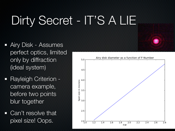
It turns out that we can’t, really. If we look at the airy disk diameter formed from a perfect diffraction limited HTC One X or S camera system (the parameters I chose since at the time this was, and still is, the best system on paper), we get a spot size around 3.0 microns. There’s some fudge factor here since interpolation takes place thanks to there being a bayer grid atop the CMOS that then is demosaiced, more on that later, so we’re close to being at around the right size, but obviously 1.1 microns is just oversampling.
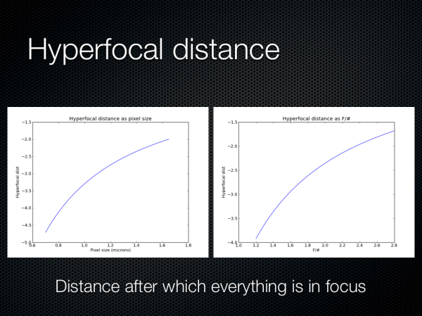
Oh, and also here are some hyperfocal distance plots as a function of pixel size and F/# for the same system. It turns out that everything is in focus pretty close to your average smartphone, so you have to be petty close to the subject to get a nice bokeh effect.
The Image Signal Processor (ISP)
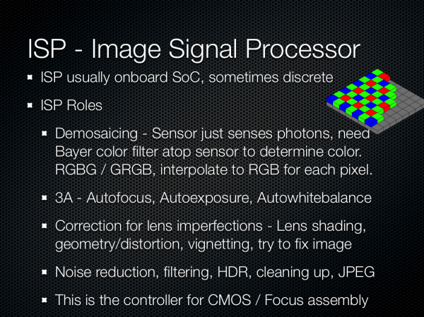
So what purpose does ISP have? Well, pixels are sensitive to light between some set of wavelengths, essentially they’re color agnostic. The way to get a color image out is to put a filter on top, usually a bayer pattern color filter, then interpolate the color of the pixels adjacent. Your 8 MP CMOS doesn’t sense red green and blue for each pixel, it senses one color for each, then ISP guesses the color based on what’s next to it. This is called demosaicing, and it’s probably the primary job of ISP, and there are many secret sauce methods to computing this interpolated image. In addition ISP does all the other housekeeping, it controls autofocus, exposure, and white balance for the camera system. Recently correcting for lens imperfections like vignetting or color shading imparted by the imperfect lens system (which you’ll add right back in with instagram, you heathen) has been added, along with things like HDR recombining, noise reduction, other filtering, face or object detection, and conversion between color spaces. There’s variance between the features that ISP does, but this is really the controller for getting that bayer data into a workable image array.
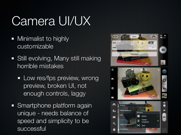
Obviously the last part is the human interface part of the equation, which is an ongoing pain point for many OEMs. There are two divergent camps in smartphone camera UX – deliver almost no options, let the ISP and software configure everything automatically (Apple), and offer nearly every option and toggle that makes sense to the user (Samsung). Meanwhile other OEMs sit somewhere in-between (HTC, others). The ideal is an opt-in option for allowing users to have exposure control, with safe naive-user defaults. There are still many players making horrible, almost unthinkable mistakes in this area too. I wrote about how the iPhone 5 crops the preview to a 16:9 size, yet captures a 4:3 image, and later was amazed to see the AOSP camera UI on the Nexus 4 deliver an arbitrary shape (not even 16:9 or something logical) crop in the preview, and also capture a 4:3 image. Composition unsurprisingly matters when taking a photograph, and it’s mind-blowing to see established players blow off things like preview. In addition, preview framerate and resolution can be an issue on some platforms, to say nothing of outright broken or unstable user interfaces on some devices. Many OEMs have been thrust into crafting a camera UI who really have limited to no camera experience — previously it was a feature to have a camera period, much less controls. As the smartphone evolves from being a camera of convenience to the primary imaging device for most people, having robust controls for when ISP and auto exposure functionalities fail will become important. Right now camera UI and UX is rapidly changing from generation to generation, with more and more serious toggles being added. I don’t think any one player has a perfect solution yet.
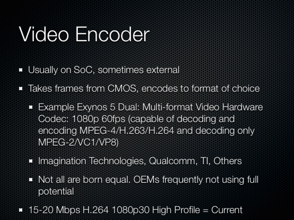
For video we need to also consider the encoder. The pipeline is much the same, though the ISP will usually request a center crop or subsample from the CMOS, depending on the capabilities of the sensor. The encoder takes these images and compresses them into a format and bitrate of the OEM or user’s choice, basically H.264 at present. Not every encoder is the same, as Ganesh will tell you. There are a number of players in this market supplying IP blocks, and other players using what they have built in-house. Many OEMs make interesting choices to err on the side of not using too much storage, and don’t encode at the full capabilities of the encoder. This latest generation of phones we saw settle somewhere between 15 and 20 Mbps H.264 high profile for 1080p30 video.
Evaluating Image Quality
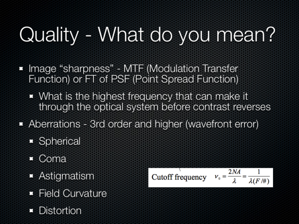
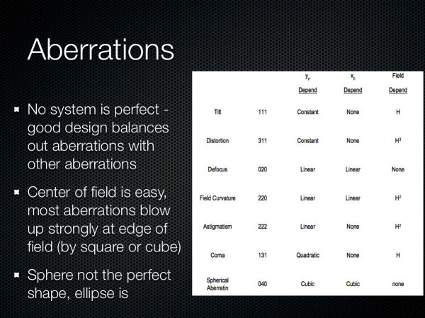
How do we evaluate quality from an image? Tomes have been written about this, and really there are many things to look for in a good image. Chief among those is really sharpness, or MTF, the modulation transfer function. That’s a discussion in and of itself, but basically MTF plots show us how much contrast we will see in a square wave at a particular spatial frequency. MTF also tells us about what the highest frequency (spatial resolution) will make it through a system, this is the cutoff frequency. There are other things to look for too, like third order aberrations.
No camera system is perfect, and good design balances one aberration against the other. If we look at field dependency the most difficult part of an image for a designer is the edges, where aberrations increase quickly.
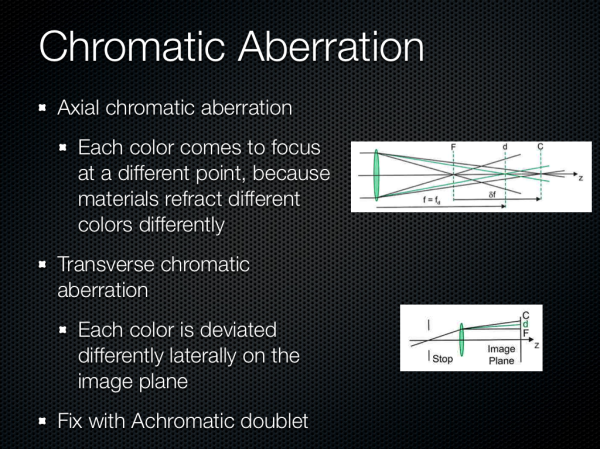
These previous aberrations have been monochromatic, there are also aberrations which exist as a function of wavelength or color. Axial chromatic we can fix with a doublet to some extent or try to minimize. Transverse is what we sometimes see with color fringing, although in most commercial systems purple fringing is often an artifact of ISP.
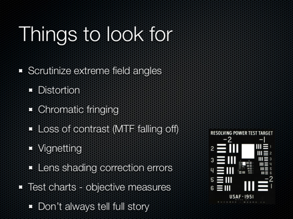
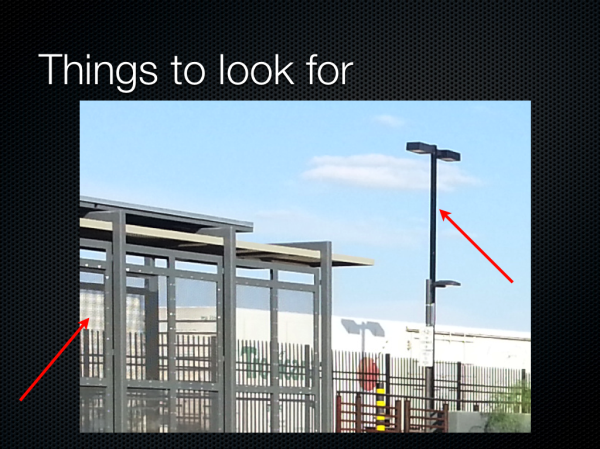
So what can we look for? Again, distortion is visible quickly since these systems in a smartphone are so wide angle. Chromatic fringing since this is annoying and something easy to notice on silhouetted subjects. Obviously sharpness is a big deal, does the image look blurry. Finally the presence of any residual vignetting and lens color shading, despite lots of gnashing of teeth from the optical designers and lots of ISP tweaking — which if you’re like my ex girlfriend you’re going to add back in with Instagram or Twitter filters to look “vintage,” you hipster. Test charts will tell us a lot, and there are many good choices, but good test scenes sometimes tell a lot more.
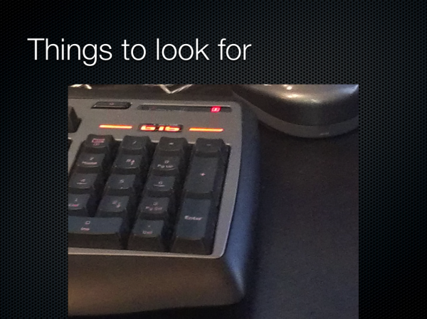
I hate pictures of keyboards in reviews since they’re the laziest subject of all to photograph when doing a review of a smartphone, but here’s one I couldn’t resist. The image is so noisy I can’t read the keys, and the totally homogenous desk looks awash with luminance noise. There isn’t much chroma (color) noise.
Here’s one I complain about a lot, huge halos around contrasty regions thanks to the sharpening kernel or unsharp mask applied to the image. This is an attempt by the OEM to add back in spatial resolution or contrast after killing it all with noise reduction, and after you see halos you won’t un-see them. We can also see some serious moire in the bottom left, partly why I love that scene.
This is a photo from a recently released device which clearly has some strong field curvature. Again the center of the image is easy to get nice and sharp, but if you look at the edges, it gets dramatically blurry. The center is easy, the edge of the field is hard.
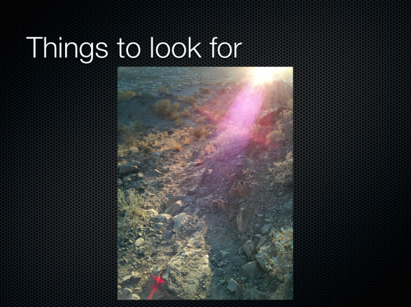
There was a very popular phone which was criticized for having some purple color stray light visible in the image when a light source was just out of the field of view. It turns out stray light is a big issue for everyone, since obviously nobody wants a huge lens hood sticking out of their phone, or at least industrial designers don’t. Well, again, this isn’t an isolated problem for just one vendor, it’s something everyone has. I believe the purple color gets picked up from a magnesium fluoride antireflection coating or some other AR coating.
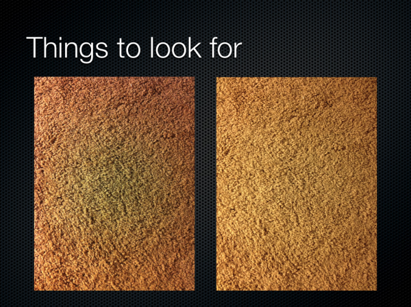
The image on the left is from a very popular device, and the image on the right is of the next generation of this popular device. The left image has a very pronounced green spot in the center, and then a definite red ring around the outside. After you see this pattern, it’s unlikely you’ll be able to un-see it. I used to play a game on Reddit looking for the green circle in people’s images, then going and checking EXIF, and about 90 percent of the time I could nail what smartphone this was coming from, just from the green spot. This is classic failure to correct for lens color shading, either their ISP couldn’t do it or they didn’t characterize it well enough, but it was fixed in the next generation. These lens shading errors are incredibly annoying when taking a photo of a subject with a flat monochromatic field, like a book, whiteboard, or so forth.
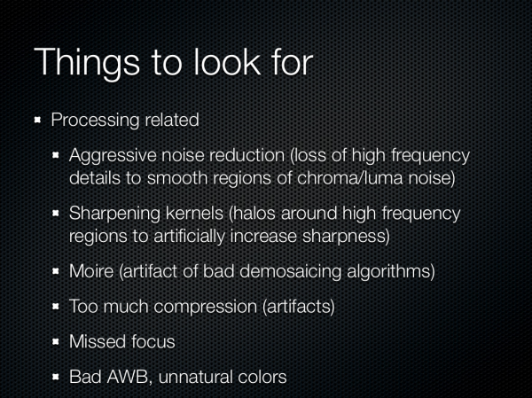
There are other things that I look for as well, aggressive noise reduction, again moire, bad auto white balance are pretty easy to spot. Another annoyance are cameras which completely miss focus, even on very contrasty scenes which should be easy to focus on with contrast based auto focus.
Trends in Smartphone Cameras
Recently, I became annoyed with the way Dropbox camera upload just dumps images with no organization into the “/Camera Uploads” folder, and set out to organize things. I have auto upload enabled for basically all the smartphones I get sampled or use on a daily basis, and this became a problem with all the sample photos and screenshots I take and want to use. I wrote a python script to parse EXIF data, then sort the images into appropriate camera make and model folders to organize things. An aberration of having this script put together was easy statistical analysis of the over four thousand images I’ve captured on smartphones from both rear and front facing cameras, and I was curious about just how much storage space the megapixel race is costing us. In addition I was curious about whether there’s much of a trend among certain OEMs and the compression settings they choose for their cameras. The plot shows a number of interesting groupings, and without even doing a regression we can see that indeed storage space is unsurprisingly being consumed more by larger images, with the 13 MP cameras already consuming close to 5 MB or more per image.
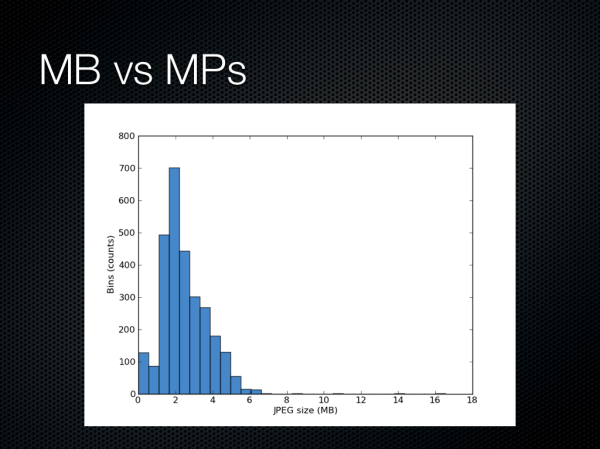
If we sort them into bins we can see that most really end up between a few KB in size to 6 MB, with the panoramas and other large stitched composites providing a long tail out to 16 MB or more.
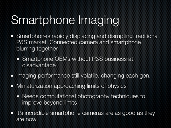
The conclusion for the broader industry trend is that smartphones are or are poised to begin displacing the role of a traditional point and shoot camera. The truth is that certain OEMs who already have a point and shoot business can easily port some of their engineering expertise to making smartphone cameras better, those without any previous business are at a disadvantage, at least initially. In addition we see that experiences and features are still highly volatile, there’s real innovation happening on the smartphone side.


