Intel D975XBX: Intel brings their Bad-Axe to Market
by Gary Key on January 26, 2006 12:05 AM EST- Posted in
- Motherboards
INTEL D975XBX: Features
The Intel SATA ports are conveniently located below the ICH7R chipset and to the left of the primary IDE connector. The SATA ports feature the new clamp and latch design. Unlike other 975x boards, the SATA ports are not color-coded for primary and secondary operation. We found the positioning of the SATA ports to be excellent when utilizing the ATI CrossFire cards in the primary and secondary PCI Express connectors.
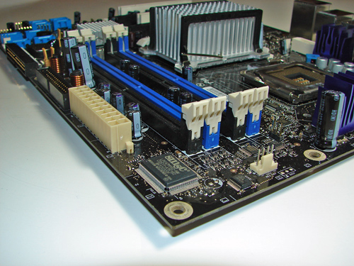
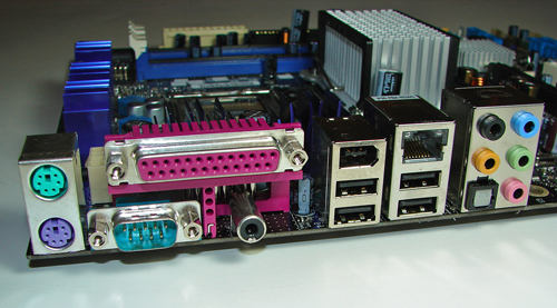
The Silicon Image SiI 3114 SATA RAID port connectors are clustered on the left edge of the board. The Intel USB connectors and chassis panel are located below the SiI 3114 port connectors and to the left of the Intel SATA port connectors. The BIOS configuration jumper block is a traditional jumper design located above the IDE port connector. The location of this jumper was acceptable during repeated usage.
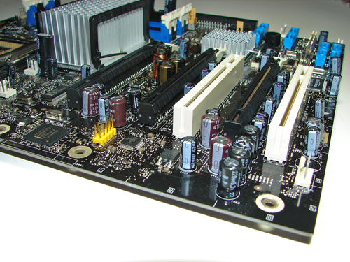
The first physical x16 connector located next to the MCH heat sink is the primary PCI Express connector and is set up for electrical routing in x16 or x8 operation. The x16 interface supports full duplex transfers up to 8 GBytes/second in x16 operation and single-ended transfers are supported up to 4 GBytes/second in x8 operation.
The next physical x16 connector is the secondary PCI Express connector and is set up for electrical routing in x8 operation. This connector also fully supports x4 and x1 PCI Express add-in cards. The final physical x16 connector is set up for electrical routing in x4 operation and fully supports x4 or x1 PCI Express add-in cards.
We did not have any issues installing an ATI X850 Crossfire Edition setup in the primary and secondary x16 PCI Express slots. This configuration will physically render the first PCI slot useless. There were no issues utilizing this slot with video cards containing single slot cooling systems.
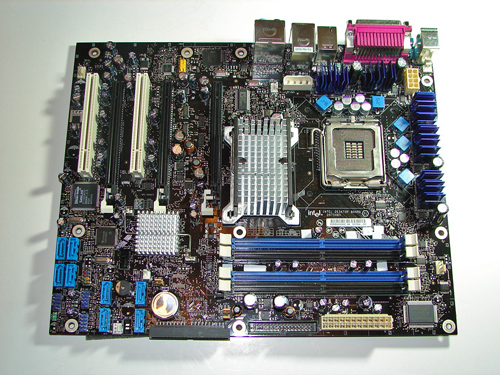
The MCH and ICH chipsets are passively cooled with heat sinks that do not interfere with any installed peripherals. In fact, this system kept the chipsets cool enough that additional chipset voltage was not a factor in our overclocking tests. Intel places the eight-pin 12V auxiliary power connector at the top of the CPU socket area, but out of the way of most aftermarket cooling solutions. However, the 4-pin auxiliary power connector is located in a difficult position and can hamper airflow with cabling that crosses over the heat sink.
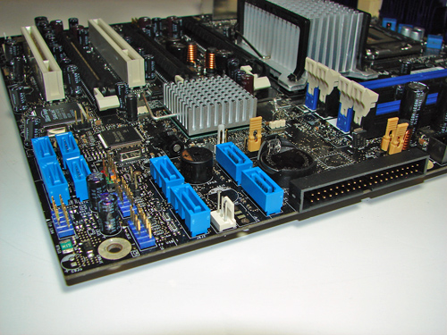
The Intel SATA ports are conveniently located below the ICH7R chipset and to the left of the primary IDE connector. The SATA ports feature the new clamp and latch design. Unlike other 975x boards, the SATA ports are not color-coded for primary and secondary operation. We found the positioning of the SATA ports to be excellent when utilizing the ATI CrossFire cards in the primary and secondary PCI Express connectors.
The Silicon Image SiI 3114 SATA RAID port connectors are clustered on the left edge of the board. The Intel USB connectors and chassis panel are located below the SiI 3114 port connectors and to the left of the Intel SATA port connectors. The BIOS configuration jumper block is a traditional jumper design located above the IDE port connector. The location of this jumper was acceptable during repeated usage.
The first physical x16 connector located next to the MCH heat sink is the primary PCI Express connector and is set up for electrical routing in x16 or x8 operation. The x16 interface supports full duplex transfers up to 8 GBytes/second in x16 operation and single-ended transfers are supported up to 4 GBytes/second in x8 operation.
The next physical x16 connector is the secondary PCI Express connector and is set up for electrical routing in x8 operation. This connector also fully supports x4 and x1 PCI Express add-in cards. The final physical x16 connector is set up for electrical routing in x4 operation and fully supports x4 or x1 PCI Express add-in cards.
We did not have any issues installing an ATI X850 Crossfire Edition setup in the primary and secondary x16 PCI Express slots. This configuration will physically render the first PCI slot useless. There were no issues utilizing this slot with video cards containing single slot cooling systems.
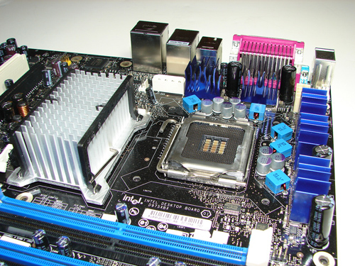
The MCH and ICH chipsets are passively cooled with heat sinks that do not interfere with any installed peripherals. In fact, this system kept the chipsets cool enough that additional chipset voltage was not a factor in our overclocking tests. Intel places the eight-pin 12V auxiliary power connector at the top of the CPU socket area, but out of the way of most aftermarket cooling solutions. However, the 4-pin auxiliary power connector is located in a difficult position and can hamper airflow with cabling that crosses over the heat sink.


34 Comments
View All Comments
LoneWolf15 - Thursday, January 26, 2006 - link
"Bad Axe" is also a city in the state of Michigan.http://en.wikipedia.org/wiki/Bad_Axe,_Michigan">http://en.wikipedia.org/wiki/Bad_Axe,_Michigan
fishbits - Thursday, January 26, 2006 - link
That they chose to call this (or anything else) "Bad Axe" will be both the funniest and saddest thing I read all day.JarredWalton - Thursday, January 26, 2006 - link
I think it's a play off of "Bad Ass" - say it fast and "axe" sounds a lot like "ass" to me. Basically, it was a codename from Intel designed to sound cool. Love it or hate it, that's what they used. Intel has geeks working there too, it seems! :)BATCH71 - Thursday, January 26, 2006 - link
I really wanted this board to be a SLI-screamer. I guess that is not the case. Next processor will be an AMD.